Takayuki HOSODA
Oct. 10, 2007
 Japanese edition is here.
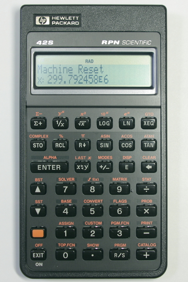
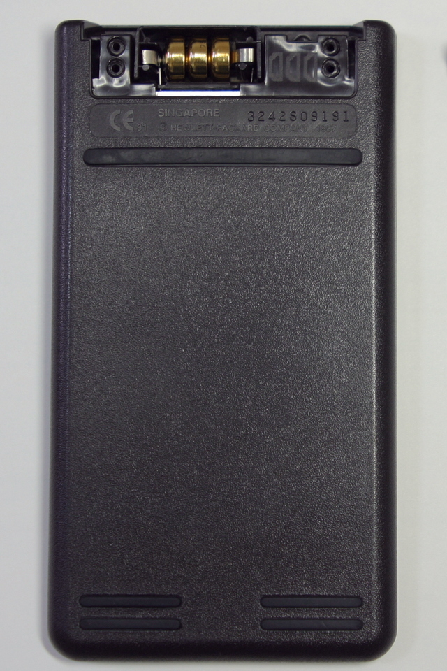
| Top view | Bottom view, Battery cover removed |
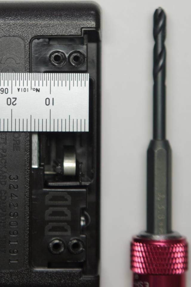
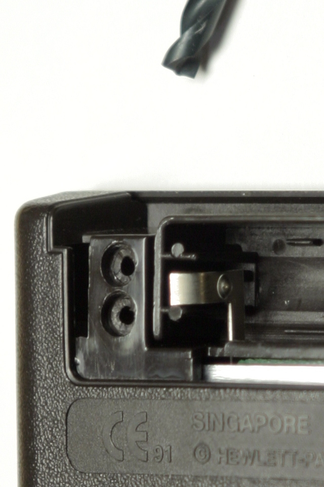
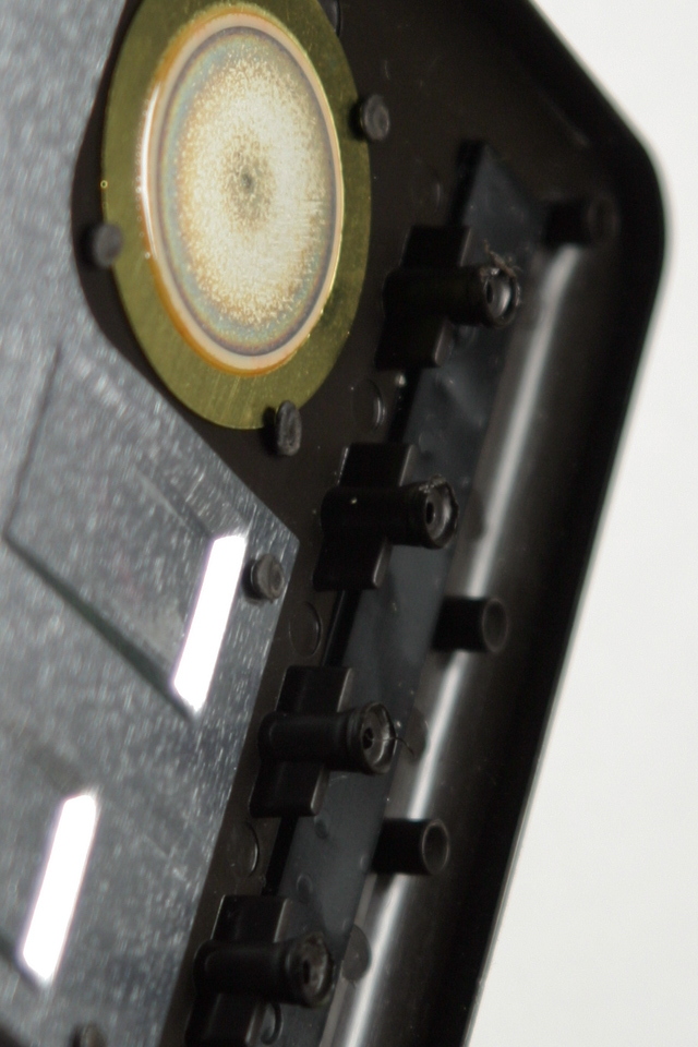
Four heat stakes and a thin plate drill (3.8mm) |
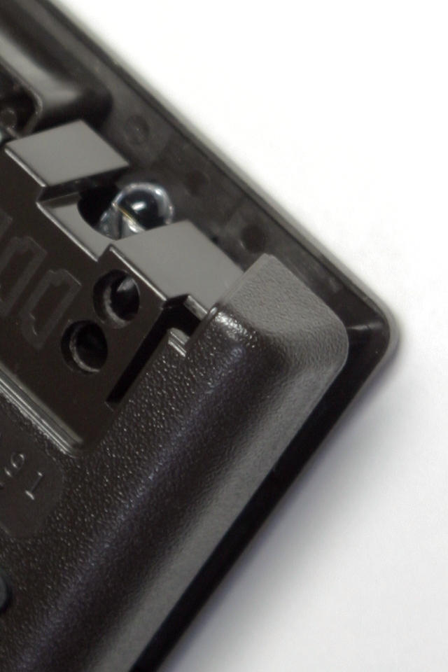
Cut out 1.5mm of the top of the heat stakes |
 |
 |
 |
 |
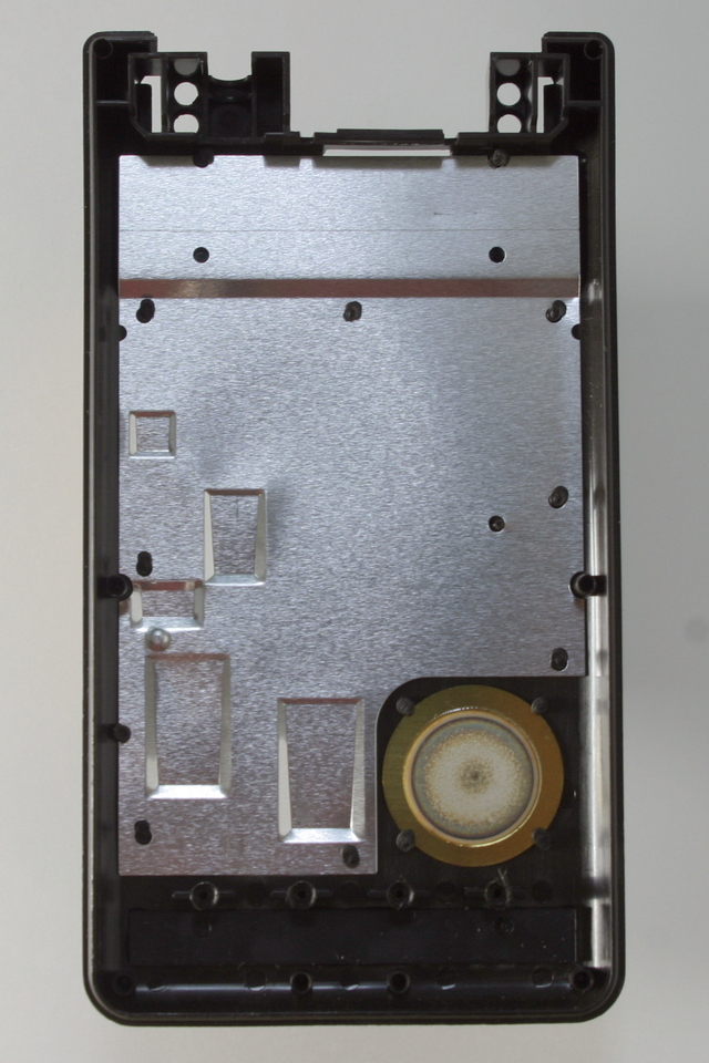
| Top end freed | Front and back apart, four hidden heat stakes*note0 |
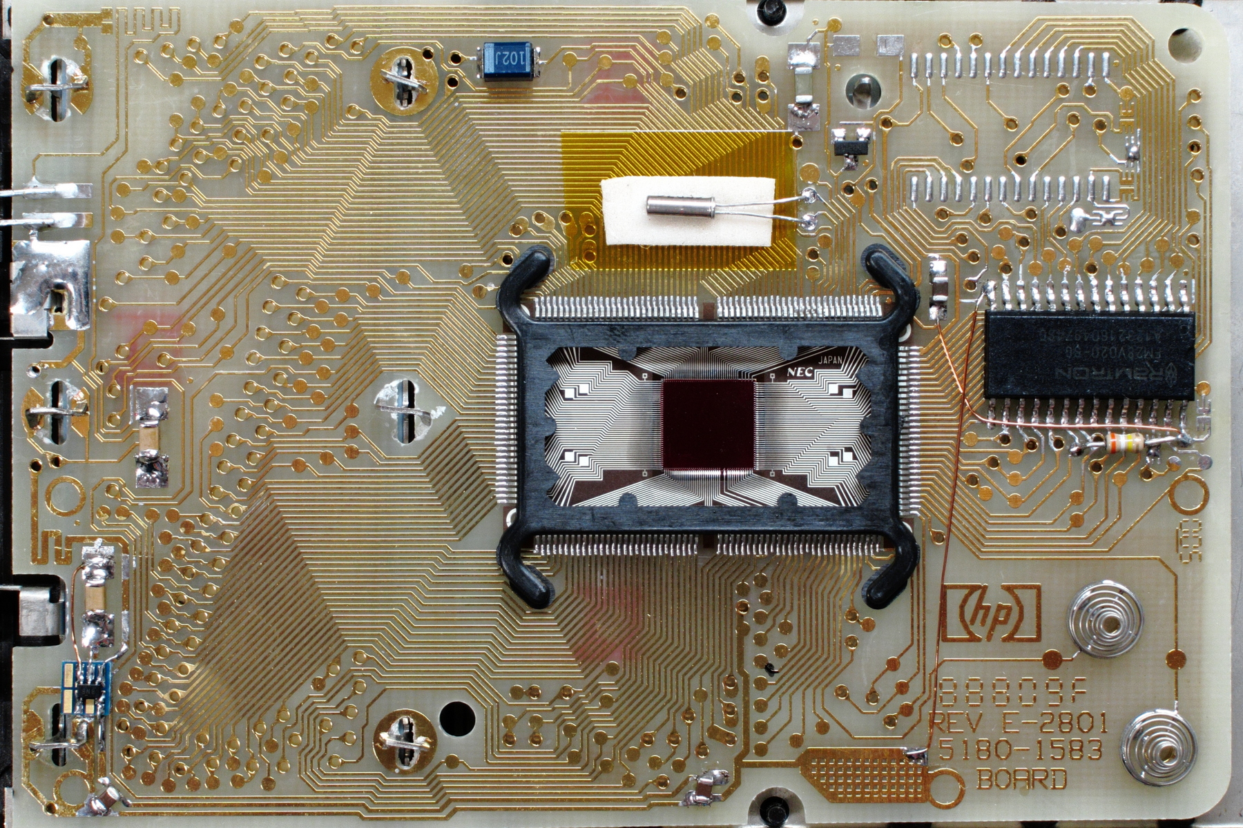
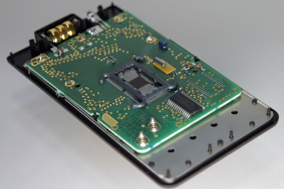
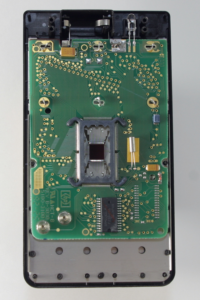
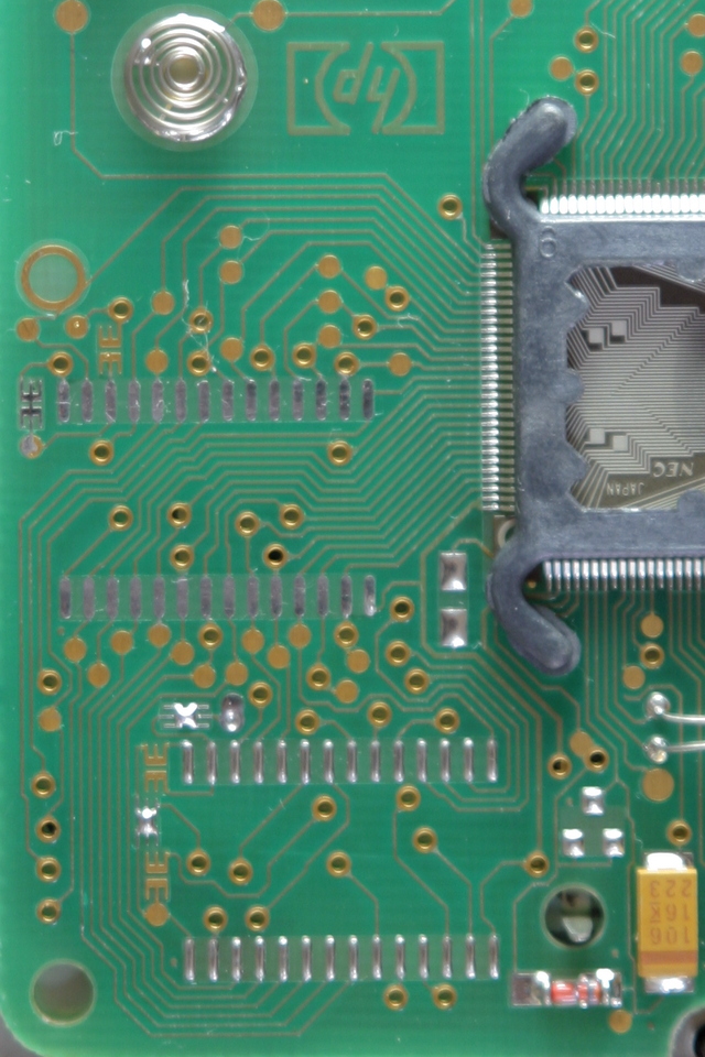
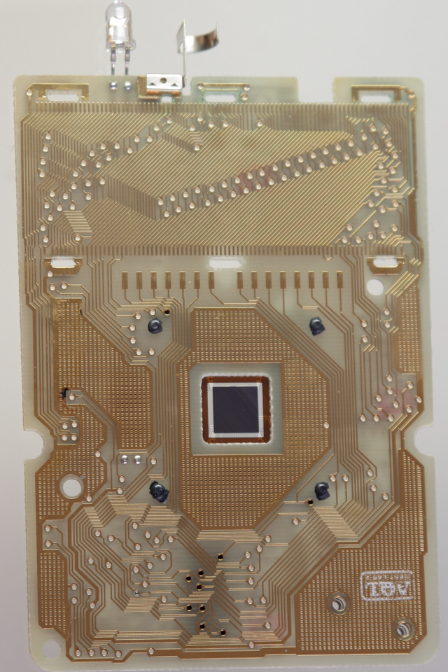
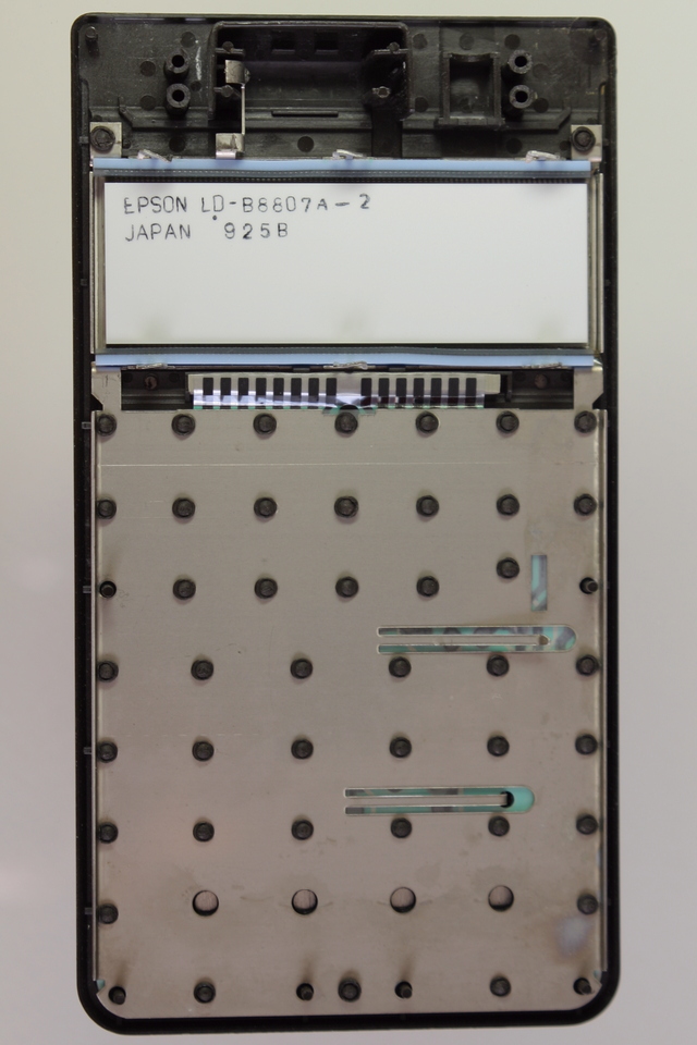
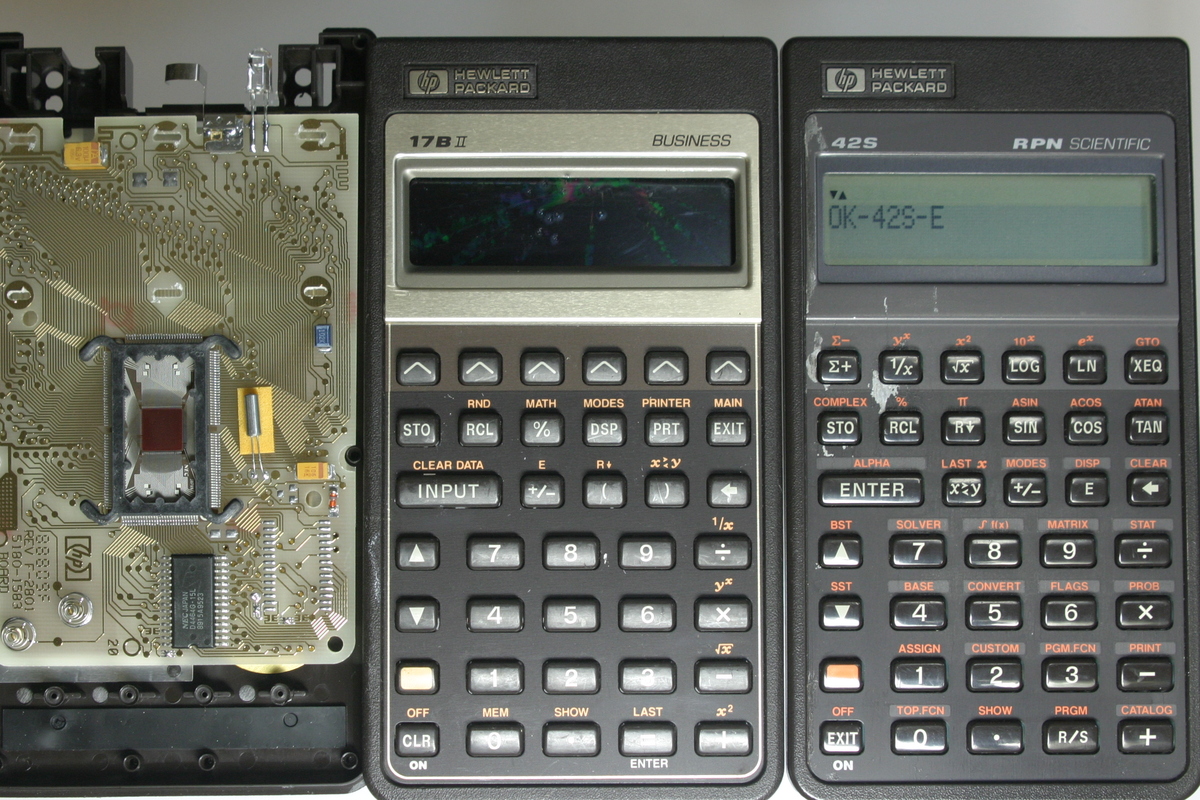
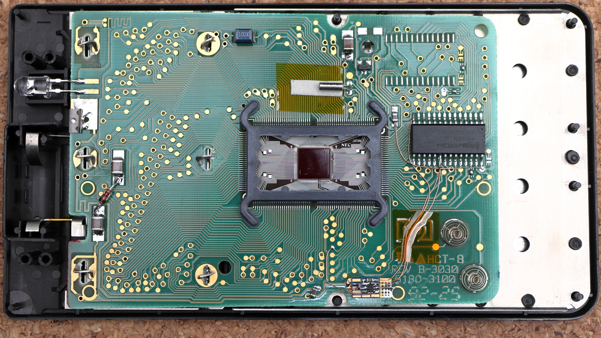
Back plate and a buzzer | Print Circuit Board, MPU with an SRAM |
 |
 |
 |
 |
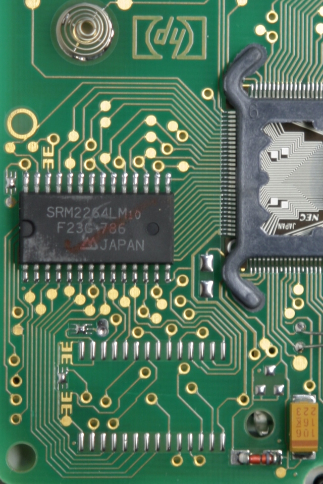
| Close up view of the SRAM and the ROM pads |
Remove the 8KB SRAM | Change the jumpers then install a 32KB SRAM, Remove fulx residue and make it clean |
|
 |
 |
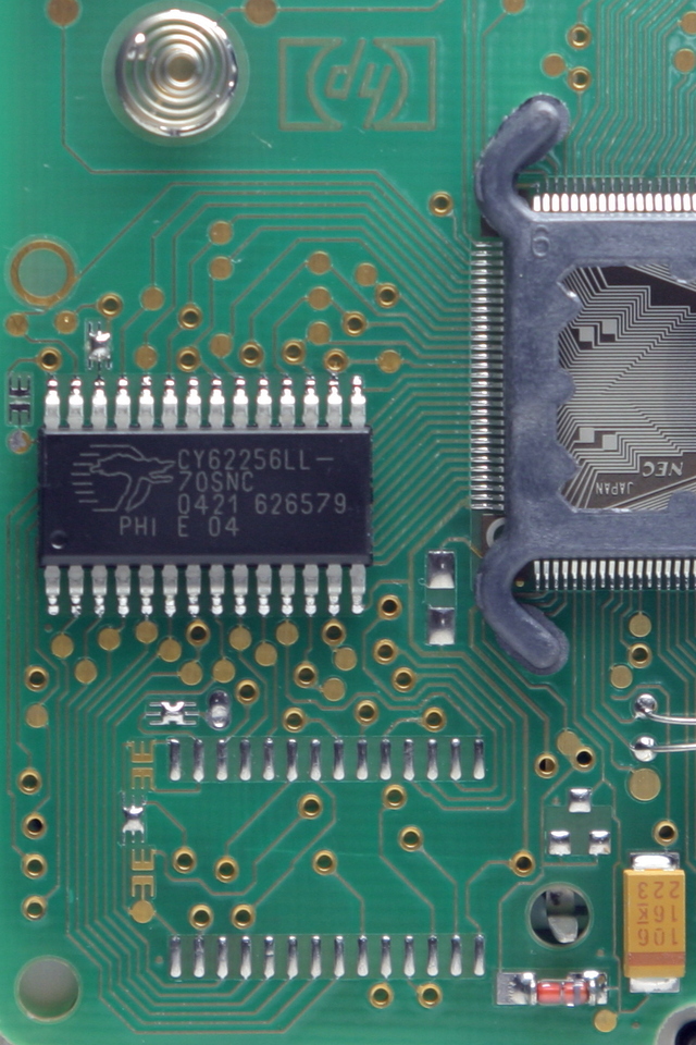 |
The original 8KB SRAM S-MOS system's low power SRAM in a standard 28-pin narrow (300mil) SOIC package. What I used here is Cypress's |
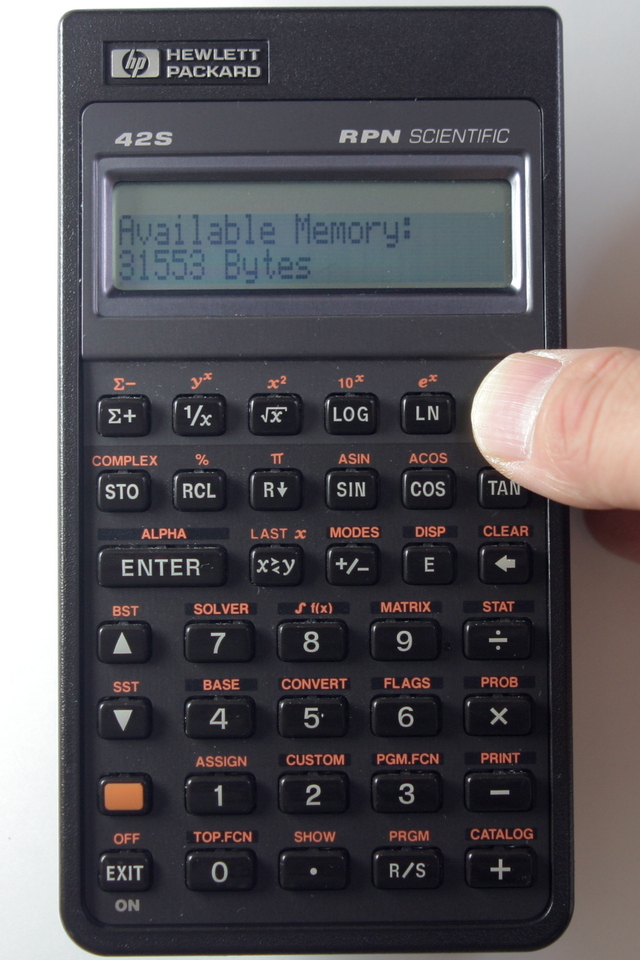
| Available Memory: 31533 Bytes (firmware revision C) |
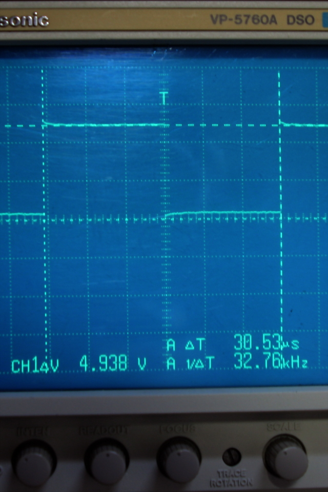
Appendix 1 *note1 Buffered clock waveform fclock = 32.768kHz |
Appendix 2 *note2 Vdd noise at SRAM and SRAM _WR waveform |
Appendix 3 *note3, *note13 Replace solid tantalum capacitors by multilayer ceramic capacitors |
 |
 |
 |
 |
*note1 : Clock frequencyAfter drilling off the upper four heat stakes, warm the back of the calculator and the metal back plate of the key pad, very tenderly to some 50 °C (120 °F), by using hair drier. This level of the temperature won't damage the calculator (however the LCD should better be isolated) but is enough to soften and deform the brim of the lower heat stakes rather easily, to get the housing apart. Then using no tools but with your own hands, grab the case stiffly and open it very slowly and carefully. With this method I have opened a total of 11 units, including 5 42S, 3 32SII, 2 17B and 1 27S without problems.
Good luck to anyone who is trying this method.
*note2 : Noise and waveformThere is a testpoint next to the crystal that seems to be a buffered output of the clock oscillator. The photo is the waveform of that point showing its frequency of 32.78kHz (actually 32.768kHz measured by a frequency counter).
*note3 : Capacitor replacement (Optional)These waveform were measured while executing the test program shown below. The Vdd noise at SRAM is acceptable and the RAM_WR waveform is not so bad.
00 { 15-Byte Prgm }
01 LBL "W"
02 STO "C"
03 CLX
04 RCL "C"
05 GTO "W"
06 .END.
*note4 : Power supply current (fclock=32.768kHz, Vbattery=4.70V(SR44×3), Ta=26°C)By replacing these solid tantalum capacitors to MLCC (multilayer ceramic capacitors), you can reduce its leakage current and also improve its life and reliability. The larger 100μF/6.3V capacitor is used as the power supply decoupling, and the other 10μF/16V capacitor is used as the filter of the voltage step up converter for LCD. The capacitors that I used here are brandnew, high performance capacitors from TDK (part code are shown below), so they are rather expensive yet. Notice that the original part pads do just fit to these C3225 size capacitors by a very narrow margin.
TDK C3225(EIA CC1210) 100μF±20%/6.3V C3225JB0J107M
TDK C3225(EIA CC1210) 10μF±20%/16V C3225JB1C106M
The Vdd noise at SRAM is not reduced so much by this capacitor replacement, as it's not intended. You can add 100nF to 1μF MLCC on the pads between RAM and the processor for its power supply decoupling.
Irun ≈ 3.3mA*note5 : Nominal capacity of SR44 is 165mAh.
Iidle ≈ 380μA
Istandby ≈ 8.9μA
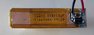
standby current monitor resistor (1kΩ±0.05%//10μF±20%)
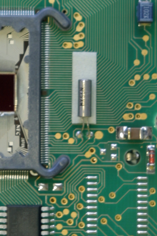
| Remove the original 32.768kHz crystal resonator |
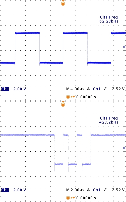
Install a 65.536kHz crystal resonator |
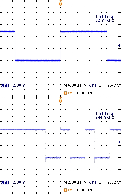
Original clock waveform clock (above) and SRAM_WR (below) |
Modified clock waveform clock (above) and SRAM_WR (below) |
 |
 |
 |
 |
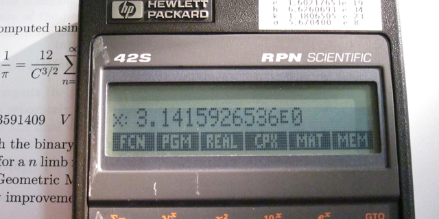
Self-test result was OK, and the results of a user program which solves some transmission line parameters were as might be expected.
With setting the speed register at 0x40300 to 0xF by using the built-in debugger, this modified 42S was able to execute the user program without error at quadruple speed of the original 42S with fresh batteries.
Self-Diagnositic-test ([EXIT]+[LN]) results at various frequency and voltage (Ta=27°C)
Ta=27°C Oscillator frequency [kHz] Comment Vbattery 65.536 100.000 131.072 4.7V O.K. O.K. O.K. Nominal voltage of SR44×3 at 20°C 3.8V Cut-off voltage of SR44×3 at -10°C 3.7V ROM O.K.
DRAM FAIL
URAM O.K.ROM O.K.
DRAM FAIL
URAM O.K.- 3.4V 3.0V cann't turn on cann't turn on Low battery indicator turns on when
Vbattery ≤ 3.0V2.9V 2.8V ROM O.K.
DRAM FAIL
URAM O.K.2.7V Cut-off voltage of LR44×3 at 20°C
Irun ≈ 5.3mA*note7 : Power supply current (fclock=65.536kHz, *(0x40300)==0xF, Vbattery=4.71V(SR44×3), Ta=23°C, SN=3242S09191 )
Iidle ≈ 440μA(typ.) (420μA/minimum contrast ~ 560μA/maximum contrast)
Iidle ≈ 440μA(typ.) (420μA/minimum contrast ~ 520μA/maximum contrast, Diode=BAR43CFILM)
Istandby ≈ 15 μA
Istandby ≈ 14.9 μA (Diode=BAR43CFILM)
Isleep ≤ 100 nA *note15
Irun ≈ 7.6mA
Iidle ≈ 480μA(typ.)
y:8
x:876
6:07.5 [min:sec] HP 42S (Rev.C) Keystroke / RPN / fosc=65.536kHz
3:28.0 [min:sec] HP 42S (Rev.C) Keystroke / RPN / fosc=65.536kHz / fast mode
136.0g + 6.6g (batteries)
I've done the same modification shown above on the other earlier model of the 42S (firmware revision A).
It works fine at the double speed, but was unable to be set to the "fast mode", so far.
and also can be set to the fast mode without problem.
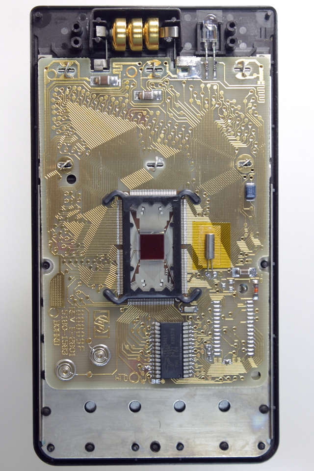
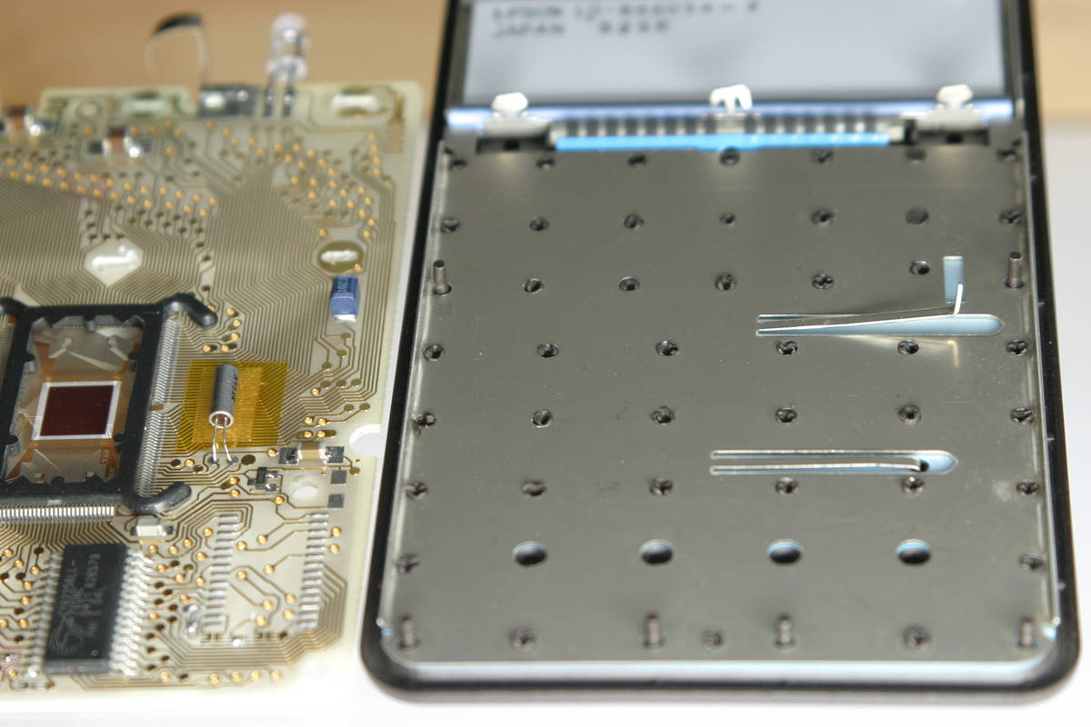
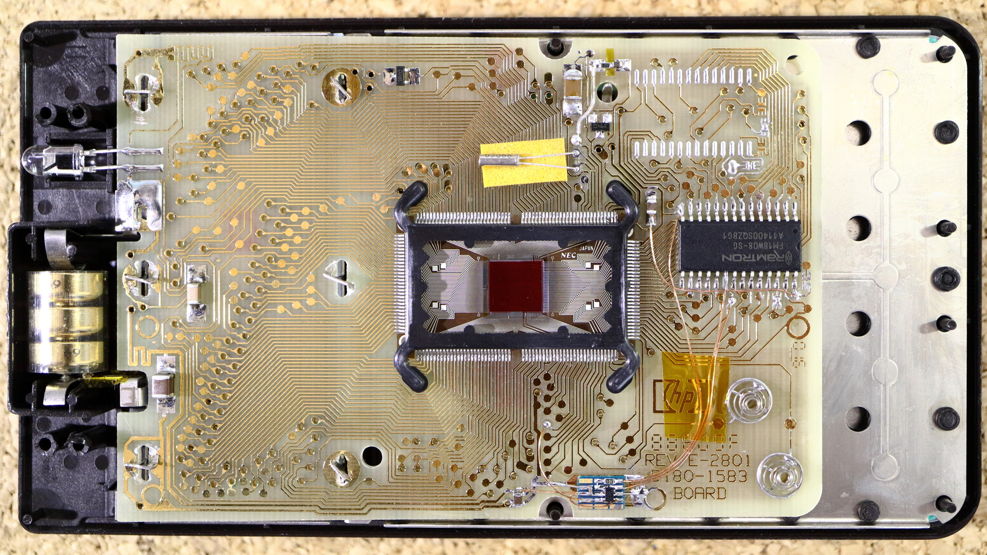
| Rear view of the PCB (firmware revision A) |
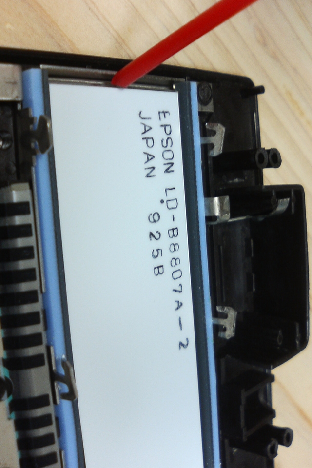
Rear view of the LCD |
Blow canned compressed gas (HFC134a) to remove dust within the LCD assembly |
Top view of the PCB after the modification |
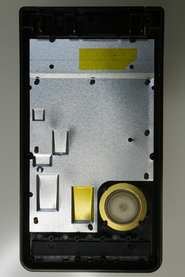
Back plate insulation Kanton® tape applied*note13 |
 |
 |
 |
 |
 |
Irun ≈ 5.0mA*note11 : Power supply current (fclock=65.536kHz, *(0x40300)==0xf, Vbattery=4.50V(SR44×3), Ta=22°C)
Iidle ≈ 440μA(typ.) (400μA/minimum contrast ~ 540μA/maximum contrast)
Iidle ≈ 380μA(typ.) (340μA/minimum contrast ~ 420μA/maximum contrast, Diode=BAR43CFILM)
Istandby ≈ 14 μA
Istandby ≈ 13.5 μA (Diode=BAR43CFILM)
Isleep ≤ 100 nA
Irun ≈ 6.8mA*note12 : Calculator Benchmark (N-queen problem) results
Iidle ≈ 440μA(typ.)
y:8*note13 : Apply Kapton® tape to the back plate
x:876
5:48.2 [min:sec] HP-42s (Rev.A) Keystroke / RPN / fosc=65.536kHz
3:30.4 [min:sec] HP-42s (Rev.A) Keystroke / RPN / fosc=65.536kHz / fast mode
If you have replaced the 100μF solid tantalum capacitor with MLCC capacitors,
tough insulation tape such as Kapton® tape should be applied on the backplate upon the capacitors to avoid accidental short circuit.
139.5g + 6.6g(batteries)*note15 : Deep sleep mode
Press [EXIT], [+] and [XEQ] simultaneously to put it into deep sleep mode.
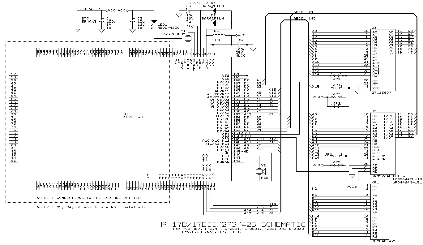
Open fullsized schematic (154KB png)
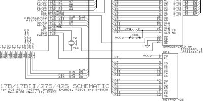
Rev.0.20 : Nov. 17 2020 : Pin assignment of the L1R2 corrected.
Rev.0.16 : Jan. 30, 2010
Rev.0.15 : Jan. 27, 2010
Rev.0.14 : Dec. 22, 2009
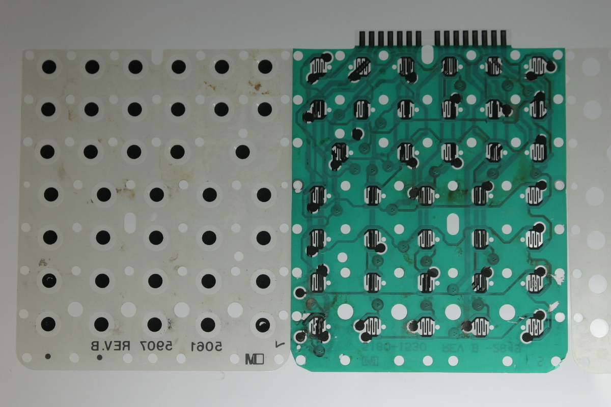
| Dead membrane switches | After transplantation of the membrane switches |
The donor and acceptor |
 |
 |
 |
The sticking-to-low-contrast LCD problem, caused by broken switching transistor in the processor, was solved by using voltage doubler circuit instead. For that purpose, the oscillator monitor output is used as its power source.
| Modified LCD bias voltage generator | Modified part of the PCB | Voltage waveforms |
 |
 |
 |
Iidle ≈ 450μA(typ.) (440μA/minimum contrast ~ 550μA/maximum contrast)
Istandby ≈ 22 μA
Isleep ≈ 660 nA
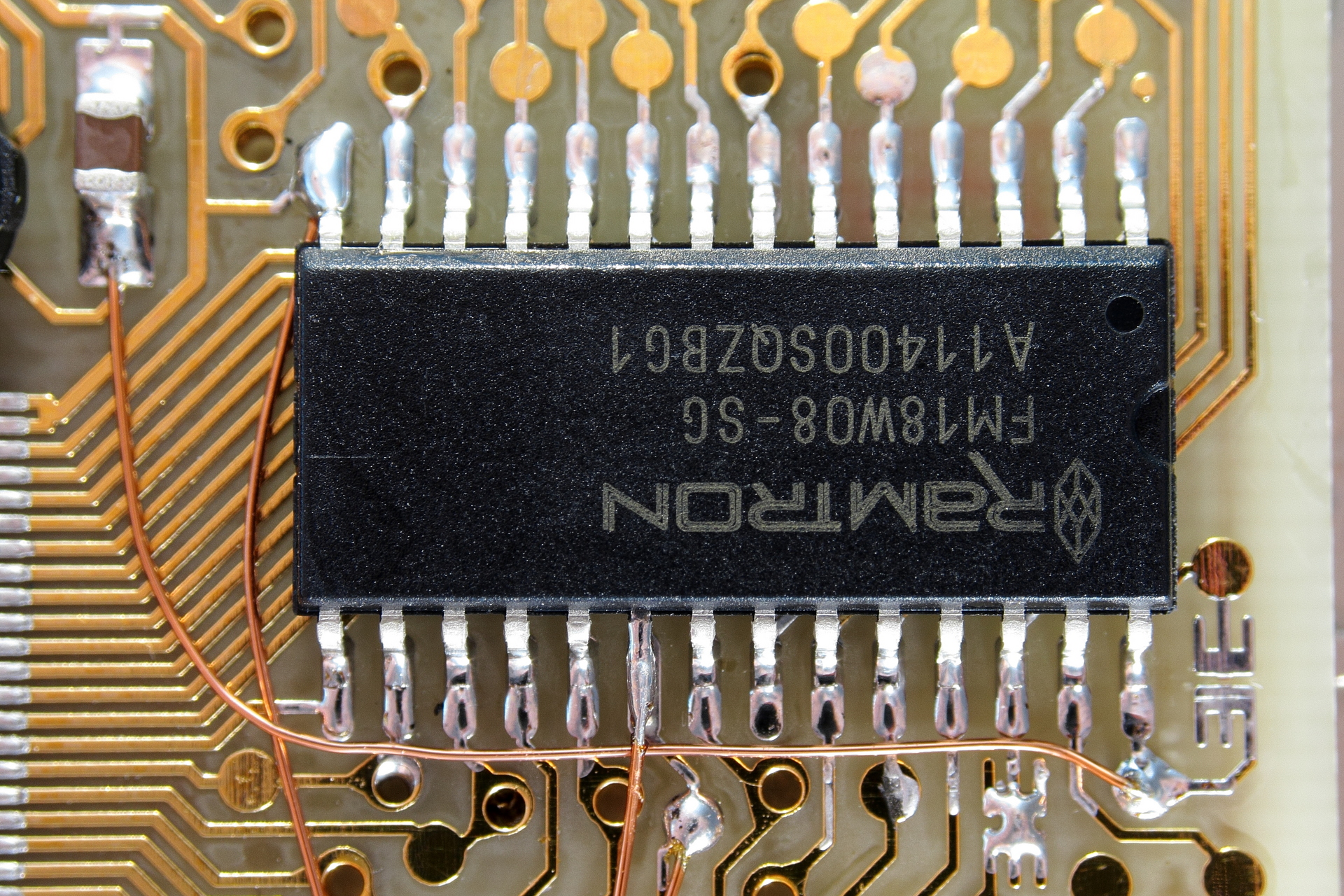
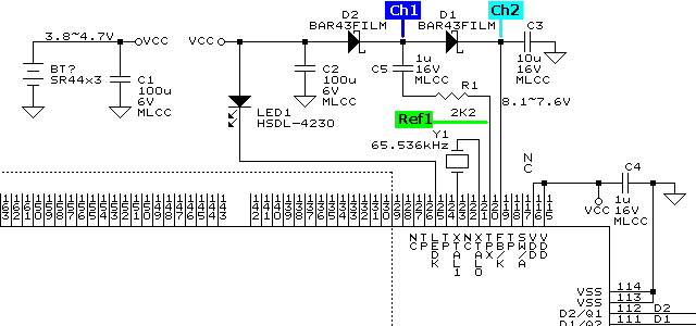
Thanks to the latest Ferroelectric Nonvolatile RAM from Cypress/Ramtron, which has wide supply voltage range of 2.7-5.5V, high endurance of 1014 read/writes, 38 year data retention and 20μA standby current, I was able to make the memory of an HP 42S nonvolatile. To utilize the NV-RAM FM18W08, slight modification is required to match the chip enable signal to that of the NV-RAM. As the *CE signal of the NV-RAM is used to latch the address value, the *CS1 from the processor must be gated by the address strobe (i.e. *CE = *CS1 & AS).
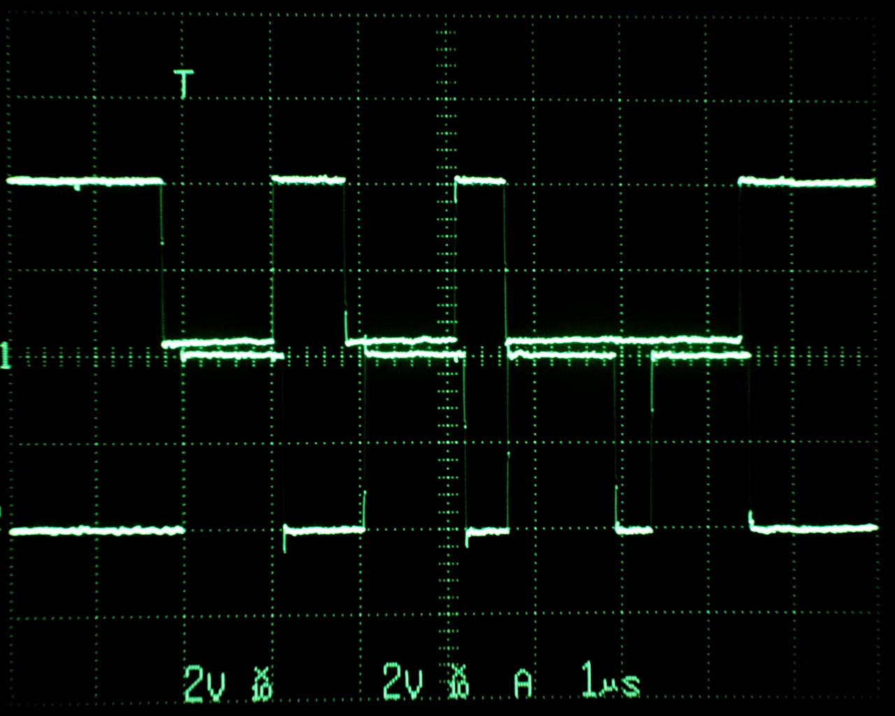
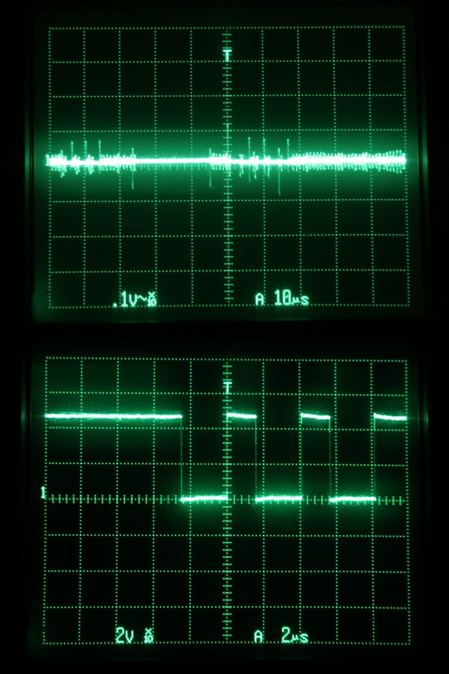
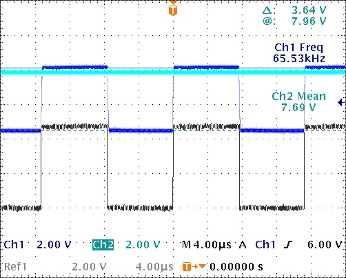
Bus control signal waveforms of an hp42S
ch1:*CS, ch2:AS (2V/div, 1μ/s, Vdd=4.2V, Ta=25°C)
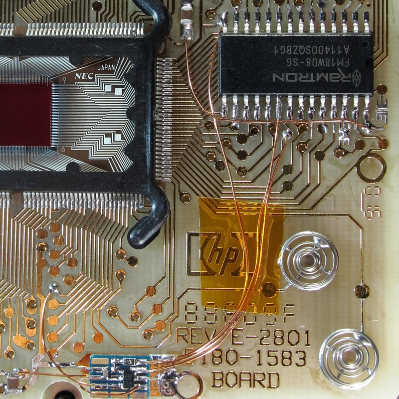
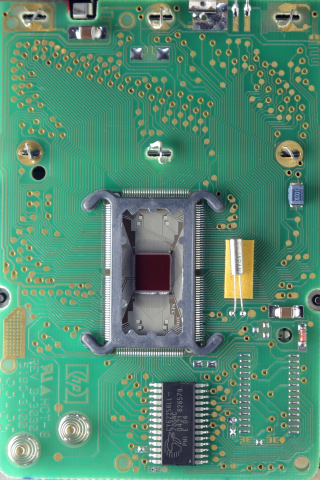
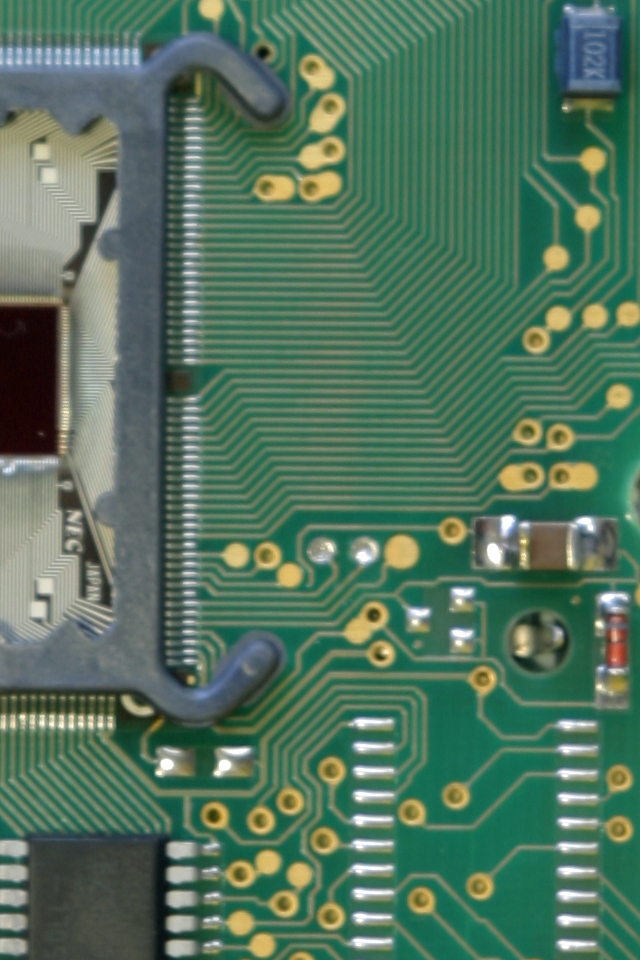
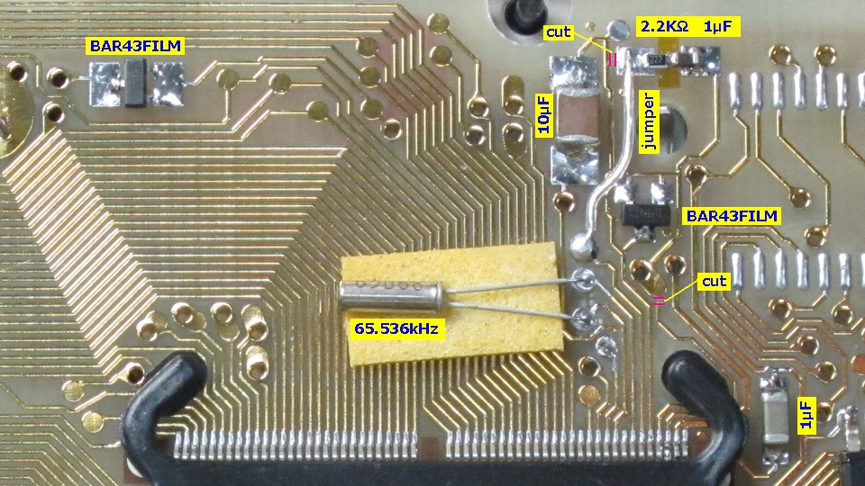
Wiring and decoupling capacitorshp42s/NV-RAM schematic diagram
Close-up view of the FRAM(FM18W08-SG)
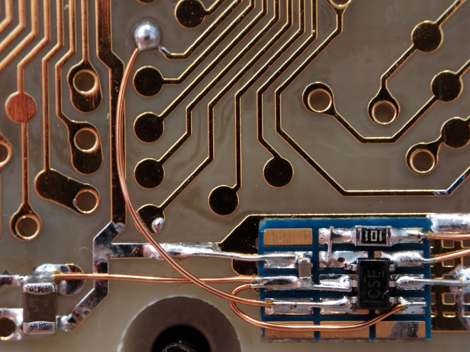
Close-up view of the multiple function gate (SN74LVC1G97)
SN=3005S02826
Click to open fullsized schematic (155KB gif)
Rev.0.19 : Dec. 11, 2013
The HP 42S/NV keep working untill supply voltage drop down to 2.9V.*note17 : Power supply current (fclock=65.536kHz, Vbattery=4.70V(SR44×3), Ta=25°C, SN=3005S02826/FM18W08-SGTR)
The contents of the calculator survived the conditions below,
- Battery removal
- Short circuit of the battery terminals
- Gradual supply voltage drop to 0V at standby state (power off)
- Gradual supply voltage drop to 0V at idle state (power on)
- Gradual supply voltage drop to 0V while running a program
Irun ≈ 3.97mA*note18 : Power supply current (fclock=65.536kHz, Vbattery=4.70V(SR44×3), Ta=25°C, SN=3242S09191/FM18W08-SGTR)
Iidle ≈ 445μA
Istandby ≈ 31.7μA
Isleep ≈ 17.5μA
Irun ≈ 4.13mA
Iidle ≈ 476μA
Istandby ≈ 22.84μA
Isleep ≈ 7.52μA
Applied the same modifications of "Double speed HP 42S with 32KB of nonvolatile RAM" to the 42s used for "Upgrading the memory of the HP 42S to 32KB". At the same time, the solid tantalum capacitor on the power line was replaced with two MLCCs and one protective Schottky diode as shown below. This diode may protect the processor and memory from ESD and reverse battery insertion.
hp42s/NV-RAM / MLCC and SiSBD schematic diagramClick to open fullsized schematic (155KB gif)Parts replacement
Rev.0.20 : Nov. 17, 2020 : Pin assignment of the L1R2 corrected.
DUT = BAT43, Ir ≈ 40 nA (Ta = 21 °C, Vr = 5 V), Vf ≈ 304mV (Ta = 21 °C, If = 2 mA)
A pullup resistor at *CE pin of FRAM is needed to keep the pin high during power cycles assuming the processor pin tri-states during the reset condition.hp42s/NV-RAM/LDO schematic diagram
FRAM, an LDO regulator, decoupling capacitors and a pullup resistor
SN=2909S32377
Click to open fullsized schematic (43KB gif)*note19 : Power supply current (fclock=65.536kHz, Vbattery=4.70V(SR44×3), Vcc=3.30V, Ta=25°C)
Rev.0.19x : Dec. 15, 2013
Isleep ≈ 133μADISCLAIMER
These modifications are experimental, and the results should not be considered guranteed. The descriptions of the modifications herein does not imply endorsement or recommendation by the author.
MoHPC HP Articles Forum, Increasing HP-42S Memory to 32K, Paul J. BroggerSEE ALSO
MoHPC HP Articles Forum, Pioneer keyboard schematic, Randy Slayer
HP Pioneer series calculator internalsAPPENDIX - Program library
HP-27S LCD transplantation
Swiss micros' DM42
Hewlett-Packard Calculator - Eric's site
www.finseth.com - HPDATAbase
www.hp42s.com - Home on the net for everything HP-42S
www.hpmuseum.org - The Museum of HP Calculators
MoHPC HP Articles Forum, Pioneer "Observational Internals", Paul J. Brogger
MoHPC HP Articles Forum, HP-42S: New Facts, J-F Garnier
HP-42S Fast Mode under program control, Gene
Cypress
TDK
Maxell

![[Mail]](/~lyuka/images/mail.gif)


 © 2000 Takayuki HOSODA.